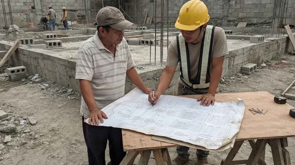
Nobody reads a structural set front to back. You start at the general notes, find a mark on the plan, and follow it to its row in the schedule. Illustrative photo.
Short answer: a structural plan set is a set of pointers. The plans (foundation, floor framing, roof framing) show where every member sits on the gridlines and give it a mark: F-1, C-1, B-1, S-1. The schedules say what each mark is: size, bars, ties. The general notes say what it's made of: concrete strength f'c, bar grade fy, concrete cover and the soil bearing value the footings were sized for. The details and sections show how the pieces join, and the title block says who is legally responsible: a civil engineer's signature and seal, PRC number and validity, and PTR, under Section 302(3) and Figure III.2 of the Revised IRR of PD 1096, with the PTR number required on plans by Section 139(e) of the Local Government Code. Read them in that order: notes, plan, schedule, detail, title block. For a building permit, the set also needs structural computations unless the building is a one-storey detached structure of 20 m² or less (IRR Sec. 302(5)(c)), and a foundation investigation with a professional report at every site, which from two storeys up must be an exhaustive geotechnical study with boreholes (NSCP 2015 Sec. 303.1).
The checker below tells you what your set is missing and why each item matters. A typical cheap two-storey set, with the schedules drawn but no computations, no soil report and thin general notes, scores 67% (8 of 12 items). After it: each sheet in the order you'd read it, a decoder for schedule callouts, the abbreviations, what the Building Official actually requires, and how to check the plans against the site and the BOQ.
Describe the building, then go through your set and mark what's there. You get a completeness score, what's missing, and why each item matters, with the rule behind it. The required items come from Section 302(5) of the Revised IRR of PD 1096 and Sections 106 and 303.1 of NSCP 2015. It checks whether a sheet exists, not whether the design on it is right.
The "structural plans" are one group in the permit set. Section 302(3) of the 2004 Revised IRR of PD 1096 assigns the civil/structural documents to a civil engineer, and Section 302(5) lists what they are: a site development plan for non-architectural structures such as sewage treatment plants, silos, elevated tanks, towers and fences; foundation plans and details and floor and roof framing plans and details, "at scale of not less than 1:100"; details and schedules of the structural elements; the structural analysis and design; boring and load tests where required; and a seismic analysis. For a two-storey concrete house, that usually comes out as something like this. Sheet numbers vary by office:
| Typical sheet | What's on it | What you use it for |
|---|---|---|
| S-1 General notes | Code edition, f'c, bar grade, cover, soil bearing value, loads, laps and hooks, legend of symbols | What every member is made of |
| S-2 Foundation plan | Gridlines, footing marks (F-1, F-2), column marks, tie or grade beams, wall footings | Where everything sits; setting out on site |
| S-2/S-3 Schedules | Footing, column, beam and slab schedules | Sizes and bars for each mark |
| S-3 Floor framing plan | Beam marks, slab panels, openings, stair | Second-floor structure |
| S-4 Roof framing plan | Truss or rafter layout, purlins, roof beams, bracing | Roof structure and its supports |
| S-5 Details and sections | Footing sections, beam-column joints, lap and hook details, stairs, lintels, CHB wall ties | How the pieces connect |
| Separate document | Structural analysis and design, soil report where required | The engineering behind the drawings; the OBO reviews it |
The code side is in NSCP 2015 Section 106. Section 106.3.1 says the design drawings "shall show a complete design with sizes, sections, relative locations and connection details of the various members," with floor levels, column centres and offsets dimensioned. Section 106.1 requires the calculations, reports, plans, specifications and inspection program to "bear the signature and seal of the engineer-of-record." If you bought a design-and-build package, this is the structural part of what you should have received.
The general notes sheet is the one most owners skip and the one site crews most often leave in the office. It's also the one sheet the code spells out. NSCP 2015 Section 106.3.2.1 says the drawings shall contain, at least:
For concrete, Section 106.3.2.2 adds the specified compressive strength f'c (the 28-day strength is the design basis), anchorage lengths, cut-off points and "location and length of lap splices," welded or mechanical splices, and whether a slab is designed as a structural diaphragm. So on the notes sheet, find these and write them down:
If the soil bearing value isn't on the notes, ask where the footing sizes came from. If the seismic basis isn't there, ask which lateral system the house was designed as. Both are answers the engineer should have without looking anything up.
The foundation plan is a view from above at footing level. Gridlines run both ways, lettered one way (A, B, C) and numbered the other (1, 2, 3), with dimensions between them. At each intersection there's a column, and around it a footing drawn as a dashed square with a mark: F-1, F-2. Wall footings along CHB walls, tie beams or grade beams (often marked TB or GB) linking the footings, and the dimensions from gridlines to property lines are also here.
The mark is a pointer. F-1 on the plan means "go to row F-1 of the footing schedule." A typical schedule row gives:
| Column | What it means | What to check on site |
|---|---|---|
| Mark | F-1, F-2 ...; how many of each is counted off the plan | The right footing at the right gridline |
| Size (L × W) | Plan dimensions of the footing, e.g. 1.20 × 1.20 m | Excavation and form size |
| Thickness (t) | Depth of the concrete pad itself, e.g. 300 mm | Measured at the form |
| Depth (Df) | Depth from natural grade line (NGL) to the bottom of footing | Measured from undisturbed ground, not from a fill |
| Reinforcement | e.g. 8-16mm Ø EW: eight 16 mm bars each way; or 16mm Ø @ 150 BW | Count both directions; 75 mm cover on blocks |
Where do those sizes come from? The column load divided by the soil bearing value from the general notes. That's why the soil value matters so much. When no exhaustive soil investigation is done, NSCP Section 304.2 says the presumptive values of Table 304-1 "shall be used," and that using them requires the foundation design engineer to have, "at the least," inspected the site and become familiar with the soil. For soils, the table values range from 50 kPa for clays and silts to 100 kPa for gravel (rock rows go higher), and mud, organic soils, peat and unprepared fill get no presumptive value at all. Our footing size calculator works through the arithmetic for your own column load.
A footing schedule with one size for every column, on a house where corner and interior columns carry very different loads, is sometimes fine and sometimes a sign that nobody sized anything. The computations answer that. The drawing can't.
A column schedule gives, for each mark (C-1, C-2), the section size (e.g. 300 × 300 mm), the main bars, and the ties, often split by storey because upper columns can be smaller. The tie line is the one to read carefully, because a proper seismic column doesn't have one tie spacing. It has two:
Most of the Philippines is Seismic Zone 4 (only Palawan except Busuanga, Sulu and Tawi-Tawi are Zone 2, NSCP 208.4.4.1), and a concrete frame that resists earthquakes by itself there has to be a special moment frame. Our column size guide explains what that does to a two-storey house. The schedule may write the tie spacing as @ 100/150, as 1 @ 50, 5 @ 100, rest @ 150, or in a detail with the zones drawn. Paste a callout below and the decoder will spell it out and flag spacings that a special moment frame wouldn't allow.
Type a column or beam callout the way it's written on your schedule. Sizes are read as millimetres. It explains the words; it doesn't check the design.
Two more things to look for. NSCP 425.7.2.2 requires ties of at least 10 mm around main bars up to 32 mm, and 12 mm around 36 mm bars. And in a special moment frame the shortest column side must be at least 300 mm (418.7.2.1). A 200 × 200 mm column drawn with 12 mm bars and 6 mm ties is detailed for something else, and it's a fair question to ask which system the design assumed.
A beam schedule is where owners get confused, because one beam has different steel along its length. It's usually a table with columns for the mark (B-1, RB-1 for roof beams, GB or TB for grade and tie beams), size (width × depth), then bars split into top and bottom, each at the support (near the column) and at midspan, and then stirrups.
The reason is physics. A continuous beam under load bends like a smile between the columns, so the bottom is in tension at midspan and needs the bottom bars there. Over each column it bends the other way, so the top is in tension and needs extra top bars at the supports. So a row like Top: 3-16mm at support, 2-16mm at midspan; Bottom: 2-16mm at support, 3-16mm at midspan is normal, not a typo. The extra top bars at the support are cut off at a distance shown in the details (the "cut-off points" of NSCP 106.3.2.2).
In a special moment frame beam, NSCP 2015 adds rules you can check on the schedule:
A stirrup line reading 10mm Ø: 1 @ 50, 8 @ 100, rest @ 200 tells you the first stirrup sits 50 mm from the column, eight more follow at 100 mm, and the rest are at 200 mm. Measure whether the close zone covers twice the beam depth: a 400 mm deep beam needs about 800 mm of close stirrups at each end.
The slab schedule (or a slab plan with notes) gives each panel's mark (S-1, S-2), thickness, and bars in the short and long directions, top and bottom. Main bars run the short way on one-way slabs. Top bars over the beams, with their extension into the panel, are the ones crews most often flatten by walking on them. Our slab thickness calculator shows the NSCP minimum thickness for a panel.
The roof framing plan shows the trusses or rafters and their spacing, purlins, bracing, the roof beams they sit on, and how they're anchored. NSCP 104.3.3 requires anchorage of the roof to walls and columns "to resist the uplift and sliding forces" from the prescribed loads, so look for a connection detail at the truss seat, not just a line on a plan. With steel trusses, the member sizes and connections should be on the sheet. "By fabricator" with nothing else means nobody designed the roof.
A section mark on a plan is a cut line with a bubble at the end. The common convention is a split circle: the top number is the section's name, the bottom is the sheet it's drawn on. "1 over S-3" means "section 1, drawn on sheet S-3." The arrow shows the direction you're looking. A detail mark works the same way for an enlarged view. That's drafting practice rather than a rule, so check the legend on your own set.
The details you want in a house set:
A set that shows every plan but no joint or lap detail leaves the most error-prone decisions to the foreman.
NSCP 106.3.2.1 requires the drawings to explain their own symbols and abbreviations, so your set's legend always wins. These are the ones you'll meet on most Philippine structural sheets, as common drafting practice:
| Abbreviation | Means | Example |
|---|---|---|
| f'c | Specified compressive strength of concrete (28-day) | f'c = 21 MPa |
| fy / fyt | Specified yield strength of main bars / of ties and stirrups | fy = 420 MPa (Grade 420) |
| DB, RSB | Deformed bar; reinforcing steel bar | 16mm DB |
| Ø, mmØ, dia. | Bar diameter | 10mm Ø ties |
| 4-16mm | Number of bars, then size | four 16 mm bars |
| @ | Spaced at (centre to centre) | @ 150 |
| o.c. | On centre | 200 o.c. |
| EW / BW | Each way / both ways | 12mm Ø @ 150 EW |
| EF | Each face (walls) | 10mm Ø @ 200 EF |
| T&B | Top and bottom | 2-16mm T&B |
| CONT. | Continuous (no cut-off) | 2-16mm CONT. |
| TYP. | Typical: applies to all similar locations | TYP. at all columns |
| SIM. | Similar: same idea, adjust to the location | SIM. to detail 2 |
| U.N.O. | Unless noted otherwise | Cover 40 mm U.N.O. |
| CL, ℄ | Centreline (on some sets CLR = clear) | ℄ of column |
| EL. | Elevation (a level) | EL. +3.00 |
| NGL | Natural grade line | Df from NGL |
| FFL, FGL | Finish floor level; finish grade line | FFL +0.30 |
| TOF / BOF | Top of footing / bottom of footing | BOF EL. −1.50 |
| F, C, B, RB, GB/TB, S | Footing, column, beam, roof beam, grade/tie beam, slab marks | F-1, C-2, B-3 |
| STR., STRP. | Stirrups | 10mm Ø STR. |
| CHB | Concrete hollow block | 150 mm CHB |
| Df, t, L × W | Footing depth, thickness, length × width | Df = 1.50 m |
The title block, usually along the right edge or bottom of every sheet, tells you who is responsible. Section 302(3) of the Revised IRR requires the plans to be "prepared, signed and sealed over the printed names" of the licensed professionals, with a civil engineer for the civil/structural documents, and its Figure III.2 model title block has fields for the PRC number and its validity, PTR number, date and place, TIN, and the IAPOA number and O.R. number.
Which profession signs which sheet, and what the 2023 Supreme Court ruling on architectural documents settled, is in our who can sign building plans guide.
Revision block. Most sets have a small table for revisions: number or letter, date, description, and initials. It's drafting practice, not a listed IRR item, but it's how you know you're reading the current set. When the contractor and you are holding sheets with different revision numbers, one of you is building from the wrong drawing. Ask the designer to issue revised sheets with the change clouded and the revision logged, never a marked-up photo on Viber.
For the building permit, the structural documents are part of the set filed under Section 302 of the Revised IRR:
| Requirement | What it says | Source |
|---|---|---|
| Number of sets | The 2004 IRR says five sets of plans and documents; JMC 2018-01 §6.1.3(b) and the Amended JMC 2021-01 say four sets, signed and sealed per IRR 302(3). Your OBO's citizen's charter has its current count. | IRR Sec. 302(3); JMC 2018-01 §6.1.3(b); Amended JMC 2021-01 §8.2.1(b) |
| Signatory | Civil engineer for civil/structural documents | IRR Sec. 302(3)(c) |
| Licence copies | One copy of the valid licences of all professionals (PTR and PRC ID), plus one copy each of the cost estimate, specifications and structural design and analysis where applicable | Amended JMC 2021-01 §8.2.1(c) |
| Structural plans | Foundation plans and details, floor and roof framing plans and details, at not less than 1:100; details and schedules of structural elements | IRR Sec. 302(5)(b) |
| Structural analysis and design | All buildings except a one-storey, single detached building of 20.00 m² or less | IRR Sec. 302(5)(c) |
| Boring and load tests | Boring tests, and load tests if necessary, for buildings of 3 storeys and higher; also lower buildings in areas with potential geological or geotechnical hazards. The engineer's written report, with the design bearing capacity, is submitted with the application. | IRR Sec. 302(5)(d) |
| Seismic analysis | Listed as a civil/structural document | IRR Sec. 302(5)(e) |
| Evaluation | The OBO's civil/structural section evaluates the documents for general design and construction, structural design, and excavations, foundations and retaining walls | IRR Sec. 303(4) |
JMC 2018-01 was amended by ARTA-DPWH-DILG-DICT-DTI-PRC-BFP Amended JMC No. 2021-01 (signed December 2021). Its §8.2.1 keeps four sets of signed and sealed plans, cuts licence copies to one, and adds the valid IDs of the applicant and of the lot owner if they are different people. Your OBO's citizen's charter still has the final word.
NSCP 2015 sets its own expectations, and two of them are stricter than what many house permits get:
How strictly an OBO applies these to a small house varies. What doesn't vary: a set with drawings and no computations is incomplete under the IRR, and our guide to returned permit plans lists the structural comments that come back most.
Plans vs site. The plans are only useful if someone compares them with the work before it's covered. For each pour, take the schedules for that element to site and check: footing size and depth from natural grade; the bar count and size each way; column bars and ties, with the end zones measured; beam top bars at the supports and bottom bars at midspan; stirrup zones; laps in the allowed zones; cover blocks. Our pre-pour rebar inspection guide goes element by element. NSCP 107.3.2 describes the same job for the structural inspector: observe the work "for conformance to the approved design drawings and specifications" and bring any discrepancy to the constructor, then to the owner, engineer-of-record or Building Official if it isn't corrected.
Plans vs BOQ. A bill of quantities is supposed to be taken off these same sheets. Pick three items and trace them:
Where the BOQ and the plans disagree, the plans govern the quantity. Our bill of materials guide shows how the take-off is built, and the structural engineer fee guide covers what design and inspection cost.
It happens on almost every job. A column moves 300 mm for a door, the crew wants to use 12 mm bars because 16s are short at the hardware, the owner adds a room upstairs. What the rules say:
Substituting a smaller bar "because it's the same total area" may or may not work; it changes spacing, cover and development length. That's the engineer's call, not the foreman's.
What AEDO does. AEDO's licensed civil engineers check structural sets for owners before they're submitted or built: we go sheet by sheet against the IRR list and NSCP 2015, mark what's missing and what doesn't agree between plan, schedule and detail, and tell you what to ask your designer. Plan checks are quoted per set once we see the sheets. If the set has no design behind it, our 3-working-day structural design is ₱7,500 up to 150 m², then ₱50/m² up to 500 m², sealed plans and design report included. A BOQ taken off your plans is ₱3,000 to ₱8,000 by floor area, and a Single Milestone Check on site starts at ₱7,500 per visit. Plan checks and design are nationwide and remote; we build only in Negros Oriental.
Permit requirements are from Sections 302 to 309 of the 2004 Revised IRR of PD 1096 JMC 2018-01 §6.1.3 and Amended JMC 2021-01 §8.2.1; the PTR rule from Section 139 of the Local Government Code. Code requirements were read from the NSCP 2015 Volume I scan: Sections 103 (Table 103-1), 104.3.3, 104.4, 106, 107.1, 107.3.2 and 107.9 in Chapter 1; 303.1 (Table 303-1), 304.1 and 304.2 (Table 304-1) in Chapter 3; 418.6.3, 418.6.4 and 418.7.5 in Chapter 4; with cover, tie size and 418.7.2.1/418.8.2.2 as verified in our rebar inspection guide. Section 107.3.2 refers to a "Section 106.5" for as-built drawings that doesn't appear in our scan's Section 106. Abbreviations and sheet numbering are common drafting practice. AEDO prices are from our published service pages.
How do I read a structural plan as a homeowner?
Read it in this order: the general notes first (concrete strength, bar grade, cover, the soil bearing value and the code edition), then the foundation plan with its gridlines and footing marks, then the schedules that the marks point to (footing, column, beam and slab), then the details and sections, and last the title block to see who signed and sealed it. Every mark on a plan, such as F-1 or C-1, is a pointer to one row of a schedule.
What is included in a structural engineer's construction documents in the Philippines?
Section 302(5) of the 2004 Revised IRR of PD 1096 lists the civil and structural documents for a building permit: foundation plans and details and floor and roof framing plans and details, all at a scale of at least 1:100, details and schedules of the structural elements, structural analysis and design for every building except a one-storey single detached structure of 20 square metres or less, boring tests, and load tests if necessary, for buildings of three storeys and higher or in hazard areas, and a seismic analysis. NSCP 2015 Section 106 adds that the drawings must state the code edition, material strengths, the design soil strength, the design loads, the seismic design basis, an explanation of symbols and abbreviations, and the engineer-of-record's PRC licence number and expiry date.
What does 4-16mm DB, 10mm ties @ 100/150 mean on a column schedule?
Four main bars of 16 mm deformed bar, held by 10 mm ties. The @ 100/150 is usually read as ties at 100 mm near the top and bottom of the column and 150 mm in the middle, but drafting habits vary, so confirm it against the column detail. In a special moment frame, NSCP 2015 caps the spacing near the ends at one-fourth the smallest column side, six times the smallest main bar or a 100 to 150 mm limit set by the tie layout, whichever is smallest, which is 75 mm for a 300 mm column with 16 mm bars, and at the smaller of six bar diameters and 150 mm elsewhere, which is 96 mm. The confinement steel of Table 418.7.5.4 often pushes the end spacing lower still, about 55 mm for a 300 mm column with 10 mm Grade 420 hoops (f'c 21 MPa, 40 mm cover). Four 16 mm bars in a 300 mm column is also under the 1% minimum of 418.7.4.1 (900 mm²). So 100/150 with 16 mm bars would need a question to the designer.
Do I need structural computations for a building permit?
Almost always. Section 302(5)(c) of the Revised IRR of PD 1096 requires a structural analysis and design for all buildings and structures except a one-storey, single detached building or structure with a total floor area of 20.00 square metres or less. A two-storey house needs them. The computations are also what the drawings are supposed to be based on, so a plan set without them is just a drawing.
Do I need a soil test to build a house in the Philippines?
For two storeys or more, NSCP 2015 Section 303.1 requires an exhaustive geotechnical study, with at least one borehole for a footprint up to 50 square metres and two up to 500 square metres. The Revised IRR of PD 1096 separately lists boring tests for three storeys and higher and for lower buildings in areas with geological hazards. For a one-storey house NSCP still requires a foundation investigation and report at the site (Sections 303.1 and 104.4), but not the exhaustive borehole study, unless the site has questionable, expansive or other problematic soils (such as liquefiable, organic or compressible ground), groundwater at or within 1.5 m below the lowest floor, a floor below the adjoining ground, or needs piles or ground improvement, where Sec. 303.1 calls for the exhaustive investigation too. Otherwise the designer may use the presumptive values of Table 304-1 after at least inspecting the site, and the general notes should say which basis was used.
How do I know the structural plans were signed by a real engineer?
Look at the title block on every sheet: the civil engineer's signature and seal over the printed name, the PRC licence number and its validity, and the PTR number, date and place. NSCP 2015 Section 106.3.2.1 requires the engineer-of-record's licence number and PRC expiry date on the drawings, and the Local Government Code requires the professional tax receipt number on plans and designs. Then check the name and licence number on the PRC's online verification service. A seal on a set the engineer never designed is still his liability, but it is not a design.
What should I do if the construction does not match the structural plans?
Hold the affected work, write down what differs with photos, and get a written answer from the engineer of record, because only the designer can say whether a change is acceptable. Under the terms of the building permit in Section 304 of the Revised IRR, changes are submitted to the Building Official and an amendatory permit issued before that work starts, and at the end Section 309 requires as-built plans that reflect every change for the Certificate of Occupancy.
Laws, rules and code sections read for this article. External links open in a new tab.
Sheet numbering, schedule layouts, section-mark conventions and the abbreviations table describe common Philippine drafting practice; no code prescribes them beyond NSCP 106.3.2.1's requirement to explain symbols and abbreviations on the drawings. The @ 100/150 reading is a common convention, not a standard. This article is general information, not a review or design of your building.
Send us the structural sheets and the architectural floor plans. A licensed civil engineer will go through them sheet by sheet and tell you what's missing and what to ask your designer.