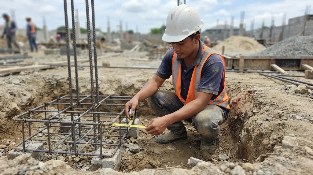
A tape from the bar to the soil tells you more about the footing than any photo of the finished pour. The bottom mat needs 75 mm of concrete under it, held up by blocks, not stones. Illustrative photo.
Short answer: the hour before the pour is the only time anyone can see the steel, so that's when it gets checked, against the plans, by the licensed architect or civil engineer the owner is required to engage under Section 308 of the Revised IRR of PD 1096. Check the bar size and count against the schedules, the grade marks on the bars, the concrete cover (75 mm under a footing, 40 mm on columns and beams, 20 mm under an indoor slab, per NSCP 2015 Table 420.6.1.3.1), the lap length and where the laps sit, 135° hooks on every tie, closer tie spacing near the ends of columns and beams, the ties through the joints, and clean steel in tight, braced forms. The number most crews get wrong is the lap. For a 16 mm Grade 420 bar in 21 MPa concrete, the checker below gives a Class B tension lap of 910 mm, about 57 bar diameters, straight from the NSCP development-length table. If your crew laps at 40 bar diameters (640 mm for that bar), that's 270 mm short.
The checker gives you the numbers for your own element and bar. Below it: why the pour is a hold point and who signs it off, then each check in the order you'd walk the site, and what to do when something fails.
Pick the element, the bar and the conditions. You get the minimum cover, the tension lap, hook sizes and the maximum tie spacing NSCP 2015 allows (in column end zones, including the confinement steel your tie size and grade can supply), with the clause for each. These are code minimums for uncoated bars in normal-weight concrete. Your structural plans can require more, and where they do, the plans govern.
A hold point is a stage the work can't pass until someone with authority has checked it. On a concrete house every structural pour is one: footings, each storey's columns, beams and suspended slab. Afterwards, cover, laps and ties can only be checked by breaking concrete, and no scan tells you a hook was bent to 90° instead of 135°.
The rules put this on the owner. Under Section 308 of the 2004 Revised IRR of PD 1096, the owner issued the building permit "shall engage the services of a duly licensed architect or civil engineer to undertake the full time inspection and supervision of the construction work" (308.1). It may or may not be the designer (308.2). A logbook is kept at the jobsite recording "the actual progress of construction including tests conducted, weather conditions and other pertinent data" (308.4), and on completion that architect or civil engineer submits it, signed and sealed, to the Building Official with a Certificate of Completion (308.5).
The permit repeats it. Section 304.5(c)(iii) makes a daily logbook kept by the supervising architect or civil engineer, open to the OBO inspector, a condition of the building permit. Section 304.5(a) cites Civil Code Article 1723: the engineer or architect who supervises is solidarily liable with the contractor if the building collapses from defective construction or inferior materials. That's why a real supervisor won't sign off on a cage he hasn't seen.
So the sign-off is a logbook entry before the pour, by the licensed supervisor: element, gridline, what was checked and corrected, signature. Not the foreman's "okay na, sir." We found no later issuance changing Section 308. Building from abroad? Our guide to building while abroad explains why a relative with a phone can't do this, and stages of house construction shows where each hold point falls.
Do the check the day before the pour, not with the ready-mix trucks already on the road.
Size and count. Count the main bars in each footing, column and beam against the schedule. A column marked 8-16mmø should have eight 16 mm bars, not four 16 and four 12. In beams, count top and bottom bars separately, at midspan and at the supports, because the schedule usually changes between them.
Grade marks. Philippine deformed bars are made to PNS 49:2020. DTI-BPS made it the reference standard (replacing PNS 49:2002) through Memorandum Circular 21-07, and set market enforcement of the new markings from 1 January 2023 under MC 21-1744. Under DTI-BPS marking rules for PNS 49:2020 bars, each bar is embossed at about one-metre intervals with:
| Grade (minimum yield, MPa) | Embossed as | Notes |
|---|---|---|
| 230 | 230 or 2 | Regular only |
| 280 | 280 or 3 | Regular or weldable (W) |
| 420 | 420 or 4 | Regular or weldable (W); plus MA/A (micro-alloyed) or QT/Q/T (quenched and tempered) |
| 520 | 520 or 5 | Regular; plus MA/A or QT/Q/T |
| 550 | 550 or 6 | Regular or weldable (W); plus MA/A or QT/Q/T |
Each bar also carries the maker's BPS pre-qualified alphanumeric logo and the bar size; each bundle has a tag with size, length, grade, lot number and PS licence or SOC number. Don't read grade by paint: DTI-BPS says there are no painting requirements on bar ends. If the plans call for Grade 420 and the bars read "3", that's Grade 280, and every lap and beam designed for 420 MPa steel is now short. "Grade 40" and "Grade 60" on site are the ASTM inch-pound names for the same two strengths; our rebar price guide lists both.
Mill certificates. NSCP Section 426.6.1.2(a): "Mill test reports for reinforcement shall be submitted." Ask for them. In a special moment frame, Section 420.2.2.5 also caps actual yield at no more than 125 MPa above the specified value and needs an actual tensile-to-yield ratio of at least 1.25, which only the mill report shows.
Condition. Rust and mill scale are acceptable if a wire-brushed sample still meets the ASTM minimum dimensions and weight per metre (426.6.1.2(b)); flaking scale that leaves the bar visibly thinner isn't. And at the pour, bars must be "clean of mud, oil, or other deleterious coatings that decrease bond" (426.6.1.2(d)). Footing cages dragged through a wet excavation get cleaned first.
Cover is the concrete between the outermost steel and the surface. Too little and the steel rusts, the rust expands and the concrete spalls. NSCP 2015 Table 420.6.1.3.1 sets the minimum for cast-in-place, non-prestressed concrete:
| Exposure | Member | Bars | Minimum cover |
|---|---|---|---|
| Cast against and permanently in contact with ground | All | All | 75 mm |
| Exposed to weather or in contact with ground (formed) | All | 20 mm to 58 mm | 50 mm |
| 16 mm and smaller | 40 mm | ||
| Not exposed to weather or in contact with ground | Slabs, joists, walls | 40 mm and 58 mm | 40 mm |
| 36 mm and smaller | 20 mm | ||
| Beams, columns, pedestals, tension ties | Primary bars, stirrups, ties, spirals, hoops | 40 mm |
Cover is measured to the tie, not the main bar. The 75 mm applies to the bottom and sides of a footing poured against soil; whether a lean-concrete blinding layer counts toward it is your engineer's call, not the crew's. And a formed column stub that will be backfilled is "in contact with ground": 50 mm for 20 mm and larger bars.
How much short is too short? Table 426.6.2.1(a) lets built cover fall short by no more than the smaller of 10 mm (12 mm where d is over 200 mm) and one-third of the specified cover; its footnote cuts that to 6 mm for formed soffits, the underside of a slab or beam. So a 40 mm column cover can't go below about 28 to 30 mm, a beam bottom below 34 mm, or a 20 mm slab cover below 14 mm.
Spacers. Section 426.6.2.2(a) requires bars "supported to prevent displacement beyond required tolerances during concrete placement": precast cover blocks or plastic spacers under every mat and on the sides of cages, and chairs under a slab's top mat. Stones roll, broken CHB crumbles, and wood rots into a channel for water to reach the steel.
A lap splice passes the force from one bar to the next through the concrete between them. Too short, and the bar pulls out before it yields. On site the number usually comes from habit, not the plans.
The length starts from the development length ℓd, simplified Table 425.4.2.2:
| Spacing and cover | 20 mm and smaller bars | 25 mm and larger bars |
|---|---|---|
| Clear spacing at least db, clear cover at least db, and code-minimum stirrups or ties; or clear spacing at least 2db and clear cover at least db | ℓd = (fyψtψe / 2.1λ√f'c) db | ℓd = (fyψtψe / 1.7λ√f'c) db |
| Other cases | ℓd = (fyψtψe / 1.4λ√f'c) db | ℓd = (fyψtψe / 1.1λ√f'c) db |
ℓd is at least 300 mm (425.4.2.1; the lap in 425.5.2.1 starts from ℓd before that minimum). From Table 425.4.2.4: λ = 1.0 for normal-weight concrete, ψe = 1.0 for uncoated bars, ψt = 1.3 for a horizontal bar with more than 300 mm of fresh concrete below it, otherwise 1.0. The longer equation in 425.4.2.3 can give less; if your engineer used it, the plans show the result.
The lap comes from Table 425.5.2.1: Class B, the greater of 1.3ℓd and 300 mm, unless the steel provided is at least twice what's required and no more than half the bars are spliced there, when Class A (1.0ℓd) is allowed. You can't confirm that on site, so check against Class B unless the plans say otherwise.
For the common house case, a 16 mm Grade 420 bar in 21 MPa concrete in the first spacing row: ℓd = 420 × 16 / (2.1 × √21) = 699 mm, and the Class B lap is 1.3 × 699 = 908, rounded up to 910 mm (57 bar diameters). Grade 280 bars: 610 mm. Grade 420 in tight spacing: 1,370 mm. Pure-compression laps can be shorter (0.071fydb, at least 300 mm, 425.5.5.1), but columns in a special moment frame must be lapped as tension splices (418.7.4.3). No lap splices for bars over 36 mm, except compression laps to a 36 mm or smaller bar (425.5.1.1, 425.5.5.3).
The location matters as much:
Two tables in NSCP 2015 Section 425.3 cover every hook you'll see:
| Hook | Used for | Minimum inside bend diameter | Straight extension |
|---|---|---|---|
| 90° standard (Table 425.3.1) | Main bars, e.g. column bars into a footing, beam bars into an end column | 6db for 10–25 mm; 8db for 28–36 mm | 12db |
| 180° standard (Table 425.3.1) | Main bars | Same as above | Greater of 4db and 65 mm |
| 90° tie hook (Table 425.3.2) | Stirrups and ties (not seismic hoops) | 4db for 10–16 mm; 6db for 20–25 mm | Greater of 6db and 75 mm for 10–16 mm; 12db for 20–25 mm |
| 135° tie hook (Table 425.3.2) | Hoops and ties, and the seismic hook | 4db for 10–16 mm; 6db for 20–25 mm | Greater of 6db and 75 mm |
Our scan prints the 90° tie-hook extension for 10–16 mm bars as "46b"; we read it as a misprint for 6db, as in the 135° row.
The seismic hook (425.3.4) is a bend of at least 90° for circular hoops "and 135 degrees for all other hoops," engaging the longitudinal bar, with the extension projecting "into the interior of the stirrup or hoop." Crossties (425.3.5) have a seismic hook at one end, at least a 90° hook at the other, and alternate end for end.
Why it matters: in an earthquake the cover spalls off first. A 90° tie hook sits in that cover, opens up, and the column bars buckle outward. A 135° hook is anchored in the core that's still there. Look at every hoop. With 10 mm ties the extension must be at least 75 mm, since 6 × 10 = 60 mm is less.
Most online checklists give one tie spacing for every column. NSCP 2015 has three sets of rules, depending on how your engineer designed the house for earthquakes:
In our experience many small provincial houses get columns detailed like ordinary tied columns, 200 × 200 mm with ties at 150 or 200 mm all the way up, whatever the drawings say. You can't fix that on pour day. You can check the cage against the plans and ask the engineer which system they designed. If it's a special moment frame:
| Rule | Special moment frame column | Intermediate moment frame column | Column not in the seismic frame |
|---|---|---|---|
| End zone length ℓo, from each joint face | Largest of column depth, 1/6 clear height, 450 mm (418.7.5.1) | Largest of 1/6 clear span, largest column dimension, 450 mm (418.4.3.3) | None under 418.14.3.2; per 418.7.5.1 if 418.14.3.3 applies |
| Hoop spacing within ℓo | Smallest of 1/4 least column dimension, 6db, and so = 100 + (350 − hx)/3, with so between 100 and 150 mm (418.7.5.3) | Smallest of 8db, 24 × tie diameter, half the least column dimension, 300 mm; first hoop within so/2 of the joint face (418.4.3.3, 418.4.3.4) | — |
| Confinement steel within ℓo | Ash/(s·bc) at least the greater of 0.3(Ag/Ach − 1)f'c/fyt and 0.09f'c/fyt, where Pu ≤ 0.3Agf'c and f'c ≤ 70 MPa; a third term otherwise (Table 418.7.5.4) | — | — |
| Spacing elsewhere | Smaller of 6db and 150 mm (418.7.5.5) | Per the shear design, Table 410.7.6.5.2 (418.4.3.5) | Zone 4: smaller of 6db and 150 mm, full height (418.14.3.2(b)); Zone 2: least of 16db, 48 × tie, least side (425.7.2.1) |
| Hooks and support of bars | 135° seismic hooks; bars supported by a hoop corner or crosstie no more than 350 mm apart (418.7.5.2) | Spiral per Section 410, or hoops per 418.4.3.3 to 418.4.3.5 (418.4.3.2) | Zone 4: hoops per 418.7.5.2. Zone 2: every corner and alternate bar held by a tie corner of at most 135°; no bar more than 150 mm clear from a held bar (425.7.2.3) |
For the checker's default (300 mm SMF column, 16 mm bars, 10 mm ties, 2.7 m clear height), the spacing limits of 418.7.5.3 give 75 mm over the bottom and top 450 mm, and no more than 95 mm in between (6 × 16 = 96, rounded down). Inside ℓo the hoops must also carry the confinement steel of Table 418.7.5.4: with a single 10 mm Grade 420 hoop and 40 mm cover that works out to about 55 mm (bc = 220 mm, Ach = 48,400 mm², two legs = 157 mm²). With Grade 280 ties it drops to about 35 mm. 12 mm hoops or a crosstie bring it back to 75 mm. The designer's spacing on the plans governs. Ties at 150 mm everywhere don't match an SMF design. Ties are at least 10 mm around bars up to 32 mm and 12 mm around 36 mm (425.7.2.2), and an SMF column is at least 300 mm on its shortest side (418.7.2.1).
The close hoops, with the same confinement steel, continue through the beam-column joint (418.8.3.1 applies 418.7.5.2 to 418.7.5.4), relaxed to half the steel and 150 mm spacing only where beams at least three-quarters of the column width frame into all four sides (418.8.3.2). Missing joint ties, left out because they're hard to place once the beam bars are in, are among the defects we find most.
It will, often. Nearly every cage we check has something: a missing joint tie, a 90° hook, a face without cover blocks. What matters is what happens next:
If the contractor refuses to fix or pours anyway, write it down, stop the progress payment for that element, and read our pakyaw vs contractor guide for who carries which risk. Before signing with anyone, check they're licensed: our PRC and PCAB verification guide takes ten minutes.
People ask this as if an engineer on the pour were optional. It isn't: Section 308 already requires the owner to engage a licensed architect or civil engineer to inspect and supervise. The real question is whether that person works for you or for the contractor. In a design-and-build or a "complete package" contract, the supervising engineer is often the contractor's own. That's legal, but it means the person checking the steel is paid by the person who placed it.
An independent check is worth it on the pours that carry the house: footings, first-storey columns, and the second-floor beams and slab. A cage with laps 270 mm short looks exactly like a good one once the forms come off. It's probably not worth paying twice if your supervising engineer is already independent of the contractor, is at every pour, and keeps a real logbook with photos. Ask to see it.
What AEDO does. AEDO's licensed civil engineers check cages before pours as part of our Project Oversight service. Our published Single Milestone Check starts at ₱7,500 per visit, with a written report, and oversight is offered nationwide because it's checking, not construction (we build only in Negros Oriental). Where a site visit isn't practical in time for the pour, we can review your plans and a pre-pour photo and video walk-through remotely. We check against your plans whoever designed them, and we tell you plainly what has to be fixed before the concrete goes in.
Code numbers were read from the NSCP 2015 Volume I scan (Sections 418, 420, 425 and 426, Section 208.4.4.1 and Table 208-11A, all read from the scan). NSCP 2015 (7th edition) is the edition we checked; if your plans cite a newer edition, it governs. Supervision and the logbook are from Sections 304.5 and 308 of the 2004 Revised IRR of PD 1096; bar grades and markings from DTI-BPS's rules for PNS 49:2020. The checker's rounding and assumptions are AEDO's and are listed under the tool.
What should I check on the rebar before the concrete is poured?
Check it against the plans' schedules: bar size and count, grade marks, concrete cover and spacers, lap length and location, 135-degree hooks on every tie, tie spacing (closer near the ends of columns and beams), ties through the joints, footing dowels, and clean steel. Then the formwork, shoring, slab thickness and conduits. Once the concrete is in, none of it can be seen again without breaking it.
How long should a rebar lap splice be in the Philippines?
NSCP 2015 Section 425.5.2.1 makes most tension laps in house work Class B: the greater of 1.3 times the development length and 300 mm. The development length comes from Table 425.4.2.2. For a 16 mm Grade 420 bar in 21 MPa normal-weight concrete, uncoated, with clear spacing and cover of at least one bar diameter and code-minimum ties, it works out to about 699 mm, so the lap is about 910 mm, or 57 bar diameters. Weaker concrete, bigger bars, top bars in deep beams or tighter spacing make it longer. If your plans show a longer lap, the plans govern.
How thick should the concrete cover over rebar be?
NSCP 2015 Table 420.6.1.3.1 sets the minimum specified cover for cast-in-place concrete: 75 mm where concrete is cast against and permanently in contact with the ground, such as the bottom of a footing; 50 mm for 20 mm and larger bars exposed to weather or in contact with ground, and 40 mm for 16 mm and smaller bars; 40 mm for beams and columns not exposed to weather; and 20 mm for slabs and walls not exposed to weather with 36 mm and smaller bars. Table 426.6.2.1(a) lets the built cover fall short by no more than 10 mm, or 12 mm in deeper members, or one-third of the specified cover, whichever is smaller.
Why do column ties need 135-degree hooks?
Because a 90-degree tie hook can pop open when the concrete cover spalls in an earthquake, and then the tie stops holding the column bars. NSCP 2015 Section 425.3.4 defines a seismic hook for stirrups, ties, hoops and crossties as a bend of at least 135 degrees for all hoops other than circular ones, with the extension engaging the longitudinal bar and projecting into the interior of the hoop. Table 425.3.2 sets the 135-degree hook extension at the greater of 6 bar diameters and 75 mm.
Who signs off the rebar before the pour?
Section 308 of the Revised IRR of PD 1096 puts the duty on the owner: whoever holds the building permit must engage a licensed architect or civil engineer to do the full-time inspection and supervision of the work, and a logbook of the actual progress, tests and weather is kept at the jobsite. That supervising professional checks the steel against the plans and records it before the pour. The contractor's foreman saying it is ready is not a sign-off. Upon completion the supervising architect or civil engineer submits the signed and sealed logbook to the Building Official.
Is it worth hiring an independent engineer for my build?
For the pours that carry the house, usually yes. Footings, columns and the suspended slab are poured once and can't be re-inspected without breaking concrete. The law already requires a licensed architect or civil engineer to supervise; an independent one works for you, not the contractor. AEDO's published Single Milestone Check starts at 7,500 pesos per visit. If your supervising engineer is already independent and at every pour, you may not need a second one.
What do the markings on Philippine rebar mean?
Under DTI-BPS marking rules for PNS 49:2020 bars, the reference standard DTI-BPS adopted through Memorandum Circular 21-07, each bar is embossed about every metre with the manufacturer's BPS pre-qualified alphanumeric logo, the bar size, and the grade either in full or as a single digit: 2 for Grade 230, 3 for Grade 280, 4 for Grade 420, 5 for Grade 520 and 6 for Grade 550. Weldable bars carry a W. Grades 420, 520 and 550 also show MA or A for micro-alloyed or QT, Q or T for quenched and tempered. There is no paint requirement on the bar ends, so read the embossing, not the colour.
Codes, rules and issuances read for this article. External links open in a new tab.
We could not read the full PNS 49:2020 text (it's sold by DTI-BPS), so its mechanical requirements aren't quoted; the grades and markings come from DTI-BPS's own published summary. We did not find a DPWH Blue Book copy we could cite for Item 404, so it isn't used. Any site practice described without a clause number is AEDO's practice, not a code rule. This article is general information, not a design for your building.
Send us the structural sheets and a few photos of the cage with a tape in them. A licensed civil engineer will check it against your plans before the concrete arrives.