NSCP 2015 (7th Edition) Section 408 — Two-Way Slabs — governs slabs reinforced for flexure in two directions: flat plates, flat slabs with drop panels, and slabs supported on beams on all four sides (the Table 408.3.1.1 thickness exemption applies only where long/short ≤ 2). This page picks up where our one-way slab calculator left off — a calculator up front for the two governing minimum-thickness tables, then the full Section 408 design-limits, required-strength, and design-strength text for reference.

What Section 408 governs. Every slab-column joint like this — thickness, drop panel, punching shear — is sized against the provisions on this page. Photo: AEDO Construction formwork at a slab-column joint.
Implements NSCP 2015 (7th Edition), Section 408 — Two-Way Slabs, Sections 408.1 through 408.5: scope, general provisions, design limits (both minimum-thickness tables), required strength, and design strength. Sections 408.6 (reinforcement limits), 408.7 (detailing), 408.8 (two-way joists), 408.10 (direct design method), and 408.11 (equivalent frame method) are separate, much longer subsections not reproduced on this page — see the note near the bottom for what that means for your design.
Before the thickness tables make sense, three definitions from Section 408.4.1 need a picture, not just words: a panel is bounded by column, beam, or wall centerlines on all sides; a column strip is a design strip on each side of a column centerline, width equal to the lesser of 0.25ℓ2 and 0.25ℓ1; a middle strip is the strip bounded by two column strips.
What is a drop panel? In a flat plate or flat slab (a two-way slab with no beams), the entire load from a panel funnels down into the slab immediately around each column — and that's the single most dangerous spot in the whole slab for punching shear, where the column can literally punch a cone-shaped hole straight through the slab. A drop panel fixes this by thickening the slab in a square or rectangular zone centered on the column, giving that critical zone more depth (and therefore more shear and moment capacity) without having to thicken the entire floor to match. It's the two-way-slab equivalent of adding a local reinforcement patch exactly where the stress is worst, instead of over-building everywhere.
A drop panel (§408.2.4) is defined by two minimums that must both be satisfied — see Figure 2 below. A shear cap (§408.2.5) does a related but narrower job — enlarging the critical section for punching shear only, without necessarily satisfying the drop panel's moment/thickness benefits. Using a qualifying drop panel is what lets a design use the thinner "with drop panels" columns of Table 408.3.1.1.
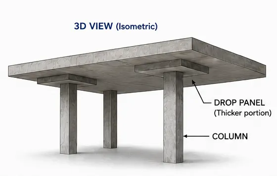
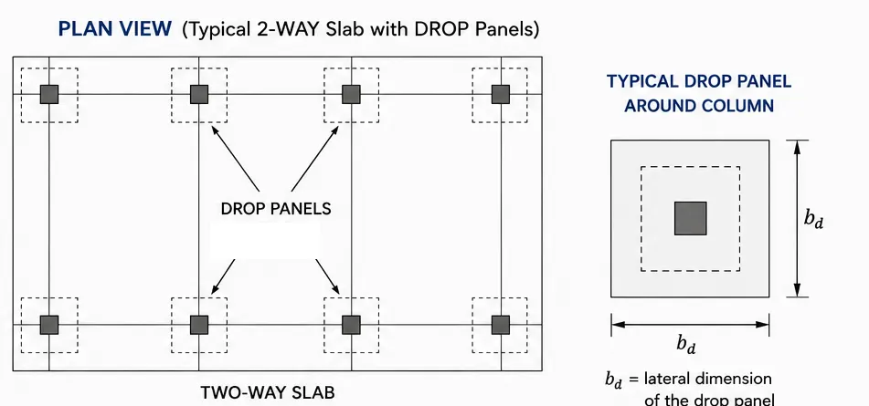
Diagrams are illustrative concept renderings, not to any particular project's scale — for the exact NSCP 2015 minimum dimensions, see Figure 2 below.
Choose whether your slab has interior beams spanning between supports on all sides, then enter spans, fy, and panel details.
Table 408.3.1.1 — Minimum Thickness of Non-Prestressed Two-Way Slabs without Interior Beams. Applies where the maximum long-to-short span ratio is 2, and thickness shall also be at least 125mm (without drop panels) or 100mm (with drop panels), whichever governs, unless the calculated deflection limits of §408.3.2 are satisfied.
| fy, MPa | Ext., no edge beam | Ext., with edge beam | Interior | Ext., no edge beam (drop) | Ext., with edge beam (drop) | Interior (drop) |
|---|---|---|---|---|---|---|
| 280 | ℓn/33 | ℓn/36 | ℓn/36 | ℓn/36 | ℓn/40 | ℓn/40 |
| 420 | ℓn/30 | ℓn/33 | ℓn/33 | ℓn/33 | ℓn/36 | ℓn/36 |
| 520 | ℓn/28 | ℓn/31 | ℓn/31 | ℓn/31 | ℓn/34 | ℓn/34 |
[1] ℓn is the clear span in the long direction, face-to-face of supports (mm). [2] For fy between table values, interpolate linearly. [3] Drop panels per §408.2.4. [4] Slabs with beams between columns along exterior edges; αf for the edge beam per §408.10.2.7 — exterior panels are "without edge beams" if αf < 0.8.
Table 408.3.1.2 — Minimum Thickness of Non-Prestressed Two-Way Slabs with Beams Spanning between Supports on All Sides.
| αfm | Minimum t |
|---|---|
| αfm ≤ 0.2 | Table 408.3.1.1 applies (a) |
| 0.2 < αfm ≤ 2.0 | Greater of: ℓn(0.8+fy/1400) / (36+5β(αfm−0.2)) and 125mm (b) |
| αfm > 2.0 | Greater of: ℓn(0.8+fy/1400) / (36+9β) and 90mm (d) |
[1] αfm is the average value of αf for all beams on edges of a panel, αf per §408.10.2.7. [2] ℓn is the clear span in the long direction, face-to-face of beams. [3] β is the ratio of clear spans, long to short direction.
What does "beams on all sides" actually look like? This is the other half of Section 408 — instead of the slab spanning unsupported between columns (flat plate/flat slab), every edge of the panel sits on a beam, and those beams carry the load down to the columns. No drop panels are used here; the beams themselves do the job a drop panel would do in a flat slab.
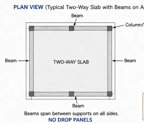
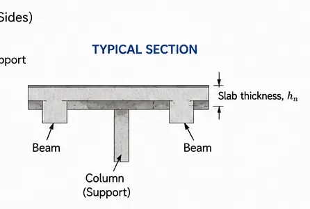
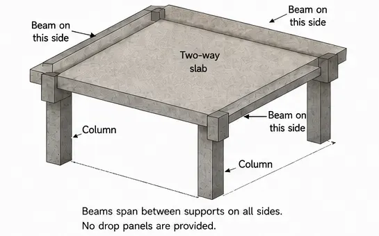
Diagrams are illustrative concept renderings, not to any particular project's scale.
§408.3.1.2.1At discontinuous edges of slabs conforming to §408.3.1.2, an edge beam with αf ≥ 0.80 must be provided, or the minimum thickness required by (b) or (d) of Table 408.3.1.2 must be increased by at least 10 percent in the panel with a discontinuous edge.
§408.3.1.3 & §408.3.1.4The thickness of a concrete floor finish is permitted to be included in t if placed monolithically with the slab, or designed composite per §416.4. If single- or multiple-leg stirrups are used as shear reinforcement, the slab thickness must be sufficient to satisfy the d requirements of §422.6.7.1.

Where the table meets the pour. Once thickness and drop panel geometry are fixed, this is the elevation it produces — the drop panel visible as the thickened band around each column. Photo: AEDO Construction two-way slab pour.
408.3.2 — Calculated Deflection Limits
408.3.2.1 Immediate and time-dependent deflections must be calculated per §424.2 and must not exceed the §424.2.2 limits for: (a) non-prestressed slabs not satisfying §408.3.1; (b) non-prestressed slabs without interior beams with a long-to-short span ratio exceeding 2.0; (c) all prestressed slabs.
408.3.2.2 For non-prestressed composite slabs satisfying §408.3.1.1 or §408.3.1.2, deflections after compositing need not be calculated; deflections before compositing must be investigated unless the pre-composite thickness also satisfies §408.3.1.1 or §408.3.1.2.
408.3.3 — Reinforcement Strain Limit
408.3.3.1 For non-prestressed slabs, εt shall be at least 0.004.
408.3.4 — Stress Limits in Prestressed Slabs (for completeness)
408.3.4.1 Prestressed slabs shall be designed as Class U with ft ≤ 0.50√f'c. Other stresses immediately after transfer and at service loads must not exceed the permissible stresses in §424.5.3 and §424.5.4. Not covered by the calculator on this page.
408.4.1 — General
408.4.1.1–408.4.1.3 Required strength per the load combinations of §405 and analysis procedures of §406; the direct design method (§408.10) is permitted for non-prestressed slabs, the equivalent frame method (§408.11) for both non-prestressed and prestressed slabs (except §408.11.6.5/408.11.6.6 don't apply to prestressed). Prestressing-induced reactions per §405.3.11.
408.4.1.4 For a slab supported by columns or walls, dimensions c1, c2, and ℓn are based on an effective support area — the intersection of the slab/drop panel/shear cap soffit with the largest right circular cone, right pyramid, or tapered wedge inside the column and capital/bracket, oriented no more than 45° to the column axis.
408.4.1.5–408.4.1.7 Column strip, middle strip, and panel definitions — see Figure 1 above.
408.4.1.8 For monolithic or fully composite construction, a beam includes the slab portion on each side extending a distance equal to the beam's projection above or below the slab (whichever is greater), capped at four times the slab thickness. 408.4.1.9 Combining gravity-load and lateral-load analysis results is permitted.
408.4.2 — Factored Moment
408.4.2.1 For slabs built integrally with supports, Mu at the support is permitted to be calculated at the face of support, except where analyzed per §408.4.2.2. 408.4.2.2 For slabs analyzed by the direct design or equivalent frame method, Mu at the support is located per §408.10 or §408.11 respectively.
408.4.2.3 — Factored Slab Moment Resisted by the Column
408.4.2.3.1 If gravity load, wind, earthquake, or other effects cause a transfer of moment between slab and column, a fraction of Msc (the factored slab moment resisted by the column at a joint) transfers by flexure per §408.4.2.3.2–408.4.2.3.5.
408.4.2.3.2 The fraction transferred by flexure, γfMsc, uses:
γf = 1 / (1 + (2/3)√(b1/b2))
408.4.2.3.3 The effective slab width bslab for resisting γfMsc is the column/capital width plus 1.5h of slab or drop panel on each side. 408.4.2.3.4 For non-prestressed slabs meeting the vug and εt limits in Table 408.4.2.3.4 below, γf is permitted to increase to the maximum modified values shown. 408.4.2.3.5 Concentrated reinforcement (closer spacing or added bars) over the column resists moment on this effective width.
| Column Location | Span Direction | vug | εt (within bslab) | Max. Modified γf |
|---|---|---|---|---|
| Corner column | Either | ≤ 0.5φvc | ≥ 0.004 | 1.0 |
| Edge column | Perpendicular to edge | ≤ 0.75φvc | ≥ 0.004 | 1.0 |
| Edge column | Parallel to edge | ≤ 0.4φvc | ≥ 0.010 | 1.25/(1+(2/3)√(b1/b2)) ≤ 1.0 |
| Interior column | Either | ≤ 0.4φvc | ≥ 0.010 | 1.25/(1+(2/3)√(b1/b2)) ≤ 1.0 |
408.4.2.3.6 The fraction of Msc not resisted by flexure is assumed resisted by eccentricity of shear per §408.4.4.2.
408.4.3 — Factored One-Way Shear
408.4.3.1 For slabs built integrally with supports, Vu at the support is permitted to be calculated at the face of support. 408.4.3.2 Sections between the face of support and a critical section at d (non-prestressed) or t/2 (prestressed) from the face may be designed for Vu at that critical section if: (a) the support reaction introduces compression into the end region; (b) loads are applied at or near the top surface; (c) no concentrated load occurs between the face of support and critical section.
408.4.4 — Factored Two-Way Shear
408.4.4.1 — Critical Section. Slabs are evaluated for two-way (punching) shear near columns, concentrated loads, and reaction areas per §422.6.4; slabs with stirrup or headed shear-stud reinforcement per §422.6.4.2; slabs with shearheads per §422.6.9.8.
408.4.4.2 — Shear Stress Due to Shear + Slab Moment. Factored shear stress vu combines vug (gravity-only shear stress) with the stress from γvMsc, where γv is per §408.4.4.2.2 and Msc per §408.4.2.3.1:
γv = 1 − γf
408.4.4.2.3 The shear stress from γvMsc is assumed to vary linearly about the centroid of the critical section per §408.4.4.1.
408.5.1.1 For each factored load combination, design strength must satisfy φSn ≥ U, including: (a) φMn ≥ Mu at all sections each direction; (b) φMn ≥ γfMsc within bslab; (c) φVn ≥ Vu for one-way shear at all sections each direction; (d) φvn ≥ vu at the two-way shear critical sections of §408.4.4.1. Interaction between load effects is considered. 408.5.1.2 φ per §421.2. 408.5.1.3 If shearheads are provided, §422.6.9 and §408.5.1.1(a) apply near the column; beyond each shearhead arm, §408.5.1.1(a)–(d) apply.
408.5.2.1 — Moment. Mn per §422.3. 408.5.2.2 For non-prestressed slabs with a drop panel, the drop panel thickness below the slab is not assumed greater than 1/4 the distance from the drop panel edge to the face of column/capital. 408.5.2.3 For prestressed slabs, external tendons are unbonded unless effectively bonded along the slab's entire length.
408.5.3 — Shear. Design shear strength near columns, concentrated loads, or reactions is the more severe of: 408.5.3.1.1 one-way shear (critical section spans the entire slab width), Vn per §422.5; and 408.5.3.1.2 two-way shear, vn per §422.6. 408.5.3.2 For composite slabs, horizontal shear strength Vnh per §416.4.
408.5.4 — Openings in Slab Systems
408.5.4.1 Openings of any size are permitted if analysis shows all strength and serviceability requirements (including deflection limits) are satisfied. 408.5.4.2 As an alternative, openings are permitted in slab systems without beams if:
(a) Any size opening is permitted in the area common to intersecting middle strips, provided total panel reinforcement is at least that required without the opening;
(b) At two intersecting column strips, not more than 1/8 the column strip width in either span may be interrupted by openings — add reinforcement equal to that interrupted, on the sides of the opening;
(c) At the intersection of one column strip and one middle strip, not more than 1/4 of the reinforcement in either strip may be interrupted — add equivalent reinforcement on the sides of the opening;
(d) If an opening is within a column strip or closer than 10h to a concentrated load/reaction area, §422.6.4.3 (no shearheads) or §422.6.9.9 (with shearheads) must be satisfied.
Section 408 continues well beyond what's reproduced here. These subsections exist in NSCP 2015 but are not included on this page — treat any specific numeric claim about them as unverified until checked against the actual code text:
This page answers "how thick does my two-way slab need to be" — the same scope as our one-way slab post. A full two-way slab design (moment distribution, column/middle strip reinforcement, punching shear reinforcement) is a materially larger undertaking that AEDO runs through BuildX NSCP Kit and on every sealed structural design project.
Case A — flat plate, interior panel, no drop panel: fy = 420 MPa, long clear span ℓn = 6.0m, short clear span 5.0m (ratio 1.2, under the 2.0 limit).
| Divisor (interior panel, no drop, fy=420 exact table value) | 33 |
| t0 = 6000mm / 33 | 181.8 mm |
| Absolute minimum (no drop panels) | 125 mm |
| Minimum thickness (t0 governs) | 181.8 mm → use 185 mm |
Case B — beam-supported panel: fy = 420 MPa, αfm = 1.0, long clear span 6.0m, short clear span 5.0m (β = 1.2), all edges continuous.
| fy factor = 0.8 + 420/1400 | 1.100 |
| Denominator = 36 + 5(1.2)(1.0−0.2) | 40.8 |
| t = 6000 × 1.100 / 40.8 | 161.8 mm |
| Absolute minimum (0.2<αfm≤2.0) | 125 mm |
| Minimum thickness | 161.8 mm → use 165 mm |
Note the beam-supported panel needs less thickness than the flat-plate equivalent at the same spans — beams on all four sides carry load the flat plate would otherwise have to span unsupported, at the cost of the extra beam formwork and reinforcement not priced into this comparison.
An engineer designs the reinforced concrete floor slabs of a 2-storey house. From the AEDO YouTube channel, uploaded 2021-02-07.

What is the minimum thickness of a two-way slab without interior beams?
Per Table 408.3.1.1: ℓn divided by a factor from 28 to 40 depending on fy, panel location, and drop panels — with an absolute floor of 125mm (no drop panels) or 100mm (with drop panels). Only applies when the long-to-short span ratio is ≤ 2.0.
What is the minimum thickness of a two-way slab with beams on all sides?
Per Table 408.3.1.2: if αfm ≤ 0.2, use Table 408.3.1.1 instead. If 0.2 < αfm ≤ 2.0, use the greater of ℓn(0.8+fy/1400)/(36+5β(αfm−0.2)) and 125mm. If αfm > 2.0, use the greater of ℓn(0.8+fy/1400)/(36+9β) and 90mm.
What is a drop panel and when is it required?
A drop panel thickens the slab locally around a column — it isn't required, but using one lets you claim the thinner "with drop panels" columns of Table 408.3.1.1. Per §408.2.4 it must project below the slab at least t/4 and extend at least ℓ/6 from the column centerline in each direction.
What's the difference between a column strip and a middle strip?
A column strip extends on each side of the column centerline a width equal to the lesser of 0.25ℓ2 and 0.25ℓ1 (§408.4.1.5); the middle strip is everything between two column strips (§408.4.1.6). They carry different shares of total panel moment under the direct design method (§408.10, not covered on this page).
What is the best NSCP 2015 calculator app for Philippine engineers?
BuildX NSCP Kit is the NSCP 2015 design suite AEDO Construction built for its own structural team, licensed to fellow engineers at recovery cost (₱499 lifetime). It runs full two-way slab design — direct design method, punching shear, column/middle strip reinforcement — beyond minimum thickness, plus one-way slabs, seismic (§208), wind (§207A/B), and concrete/steel/foundation design. Try the web preview free before buying.
The tool on this page sizes minimum slab thickness. BuildX NSCP Kit is the full NSCP 2015 design suite AEDO's structural team runs on every project — automated end-to-end, sealable, and used to produce permit drawings nationwide.
| Capability | Free Calculator (this page) | NSCP Kit ₱499 lifetime |
|---|---|---|
| Minimum thickness, both tables (§408.3.1.1/.2) | ✓ | ✓ |
| Direct design method — moment distribution (§408.10) | — | ✓ |
| Punching shear design (§408.4.4/408.5.3) | — | ✓ |
| Column/middle strip reinforcement | — | ✓ |
| One-way slab design (§407) | — | ✓ |
| Seismic (§208) & wind (§207A/B) loads | — | ✓ |
| iOS · Android · Web (one license) | Web only | ✓ |
Statutes, codes, official tools and references used or referred to in this article, linked to their source. Links open in a new tab.
Prices, cost bands and rate figures in this article are AEDO Construction's own market and practice figures for Philippine work unless a source is named beside them. Code and statute references above link to the primary text.
Minimum thickness is the starting point, not the finish line. AEDO Construction provides full structural engineering services for residential and commercial buildings in the Philippines — NSCP 2015-compliant slab, beam, column, and foundation design, structural plans, BOQ, and design-build construction.